The Four Assembly Conditions Manual Inspection Cannot Catch at Speed
At a representative mid-volume engine assembly line — throughput in the range of roughly 40 to 100 engines per hour is common, depending on plant and engine family — four independent conditions must be verified correct on every piston before it moves to engine build: circlip seating in both gudgeon-pin bore grooves; all three piston rings present with gaps staggered at 120° intervals; the gudgeon pin fully inserted with no proud end on either side; and the piston crown's directional arrow oriented correctly relative to the connecting rod. None of these can be confirmed at a glance, and at line-rate cycle times an operator has well under a minute to complete every task at the station, not just this check.
The consequence of a missed circlip is not hypothetical. In 2016, Honda issued NHTSA Campaign 16V074000, a safety recall covering roughly 42,000 Civic sedans built with 2.0-liter engines, because piston assemblies could reach the field without a properly installed piston wrist-pin circlip — a defect capable of letting the pin migrate, score the cylinder bore, and seize the engine. That is the same failure mode this app note addresses, at the same point in the process — piston sub-assembly, before engine build — and it is why OEMs increasingly specify inline, 100%-coverage verification rather than relying on operator judgement or a single-purpose poka-yoke fixture alone. IATF 16949:2016 Clause 10.2.4 (Error-proofing) calls for exactly this kind of documented, verified error-proofing on characteristics like these, including periodic functional checks on the error-proofing device itself.
Why Traditional Verification Methods Leave This Gap Open
| Method | Limitation | Impact at Assembly Station |
|---|---|---|
| Manual Torch / Visual Inspection | Operator visually inspects into the bore; classic industrial-inspection research (Drury & Fox) puts typical miss rates for this class of task at 20–30%, and fatigue compounds it over a shift | Circlip seating and ring gap angle become judgement calls, not measurements — no two operators verify identically |
| Mechanical Poka-Yoke Fixture | Prevents a wrong-sized ring or pin by geometry; cannot verify circlip seating depth or ring gap angular position | Blocks gross errors but is blind to partial seating, near-miss gap alignment, and orientation reversals |
| Single Overhead Camera | Sees crown markings and ring gaps from above; has no line of sight into the circlip groove inside the bore | The circlip — the failure mode behind the Honda recall above — remains uninspected |
| Torque / Force Sensor on Assembly Tool | Confirms that insertion force was applied; cannot distinguish a circlip fully snapped into its groove from one merely resting against it | Creates false confidence — the operator sees a pass signal on a circlip that is not fully seated |
| End-of-Line Compression / Leak Test | Tests the finished engine; can detect a ring or seating problem but not which piston, or which of the four conditions, caused it | By the time the defect is caught, correction means partial engine disassembly rather than a sub-assembly rejection — the same escalation the "1-10-100" rule describes in quality engineering, where the cost of a defect rises sharply the later it is found |
4-Camera Inline Assembly Verification — One Station, Four Conditions
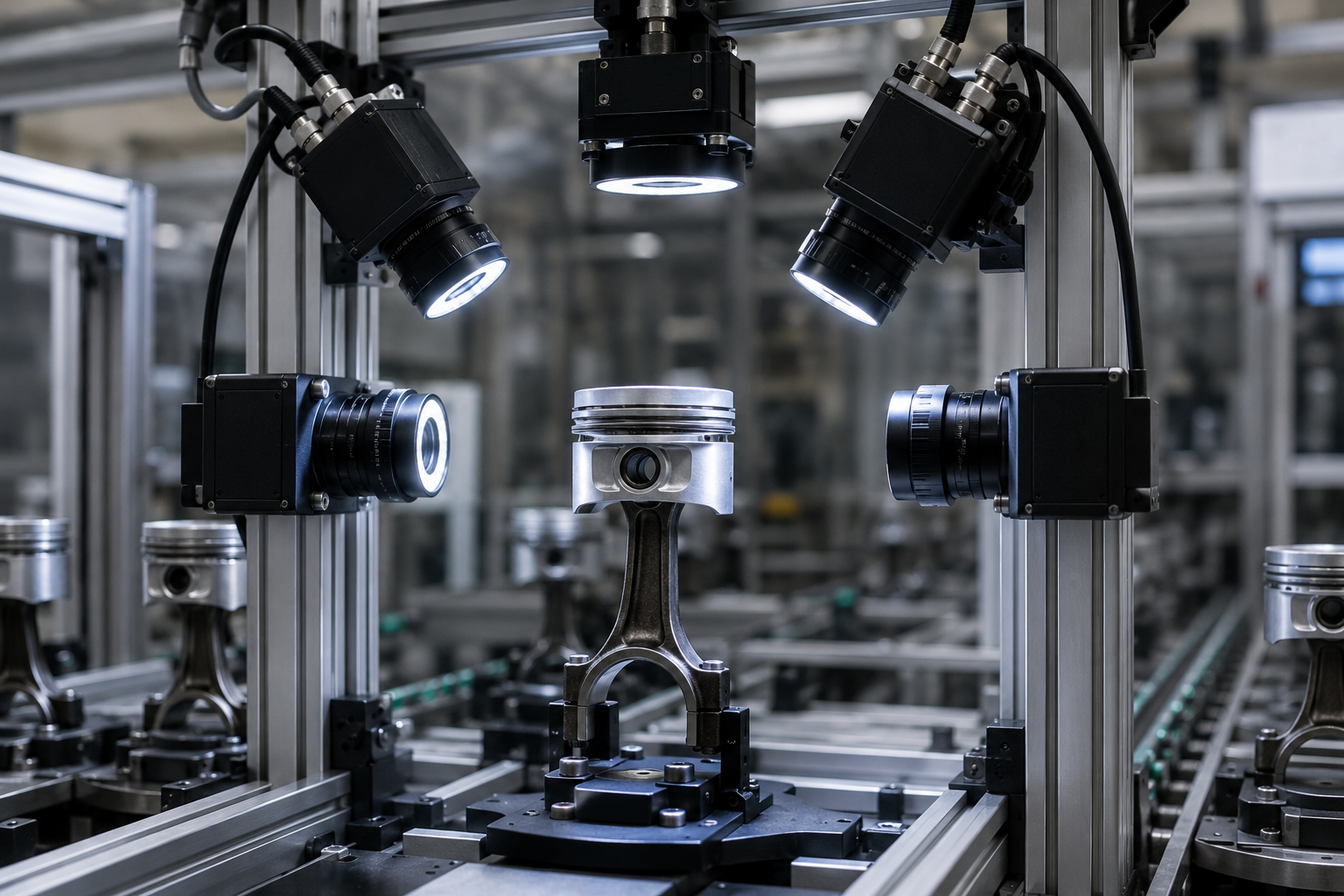
Qualitas Technologies deploys four cameras at a single indexed station embedded in the piston and connecting-rod assembly conveyor. When a piston assembly arrives at the station, the conveyor pauses for a programmable index stop — for a line in the 40–100 engines/hour range this typically falls in the low hundreds of milliseconds, but the exact figure is a design output of the line's actual cycle time, confirmed during the feasibility trial rather than fixed in advance. Camera 1 (overhead) covers ring count, ring-gap stagger angle, and crown directional arrow. Cameras 2 and 3 (left and right side) image gudgeon-pin seating depth on both ends. Camera 4 (angled bore-entry probe) images the circlip groove inside the piston boss bore.
| Assembly Condition | Camera & Technical Approach | What It Actually Verifies |
|---|---|---|
| Circlip seated (left bore) | Cam 4 bore-probe · profiles the circlip against the groove geometry | A seated circlip sits flush in the groove; one resting on top of it presents a different profile — a geometric distinction, not a brightness threshold |
| Circlip seated (right bore) | Cam 4 bore-probe · mirror/beamsplitter captures both grooves in one exposure | The same geometric check applied to both bores without a second index stop |
| Piston ring 1 — present & oriented | Cam 1 overhead · groove-occupancy check plus TOP-marking read | Confirms a ring occupies the groove and that any directional or TOP marking matches the piston's recipe |
| Piston ring 2 & 3 — present & gap position | Cam 1 overhead · radial gap-angle measurement | Measures the actual gap angle against the drawing tolerance rather than relying on an operator's eye; the measurement resolution is set for the specific optics and working distance during the design phase |
| Gudgeon pin depth — both sides | Cam 2 / Cam 3 side-mounted · sub-pixel edge detection on pin end vs. boss face | Sub-pixel edge detection commonly resolves position to a small fraction of a pixel; the real-world micron equivalent depends on the optics and working distance chosen for the station and is confirmed during the design review, not assumed up front |
| Piston crown orientation | Cam 1 overhead · deep-learning arrow-direction classifier, trained per variant | Classifies which way the arrow points across the piston's variant family; classification accuracy for the specific part and marking is validated against production samples during the feasibility trial before the station is specified as production-ready |
Expected Outcomes & Return on Investment
The system is designed to close the coverage gap above: every piston, every shift, checked against a fixed geometric standard rather than an operator's judgement, which the inspection literature shows degrades measurably over a shift. Return on investment scales with two inputs specific to each plant — the line's actual engines-per-hour rate, which sets the camera and lighting budget, and the real cost of an engine-level rework or field failure, best modelled from the customer's own warranty and rework data rather than a generic industry figure. As a reference point for that second input, the widely cited "1-10-100" rule in quality engineering holds that the cost of a defect grows by roughly an order of magnitude at each stage it escapes detection — from the assembly cell, to end-of-line test, to a warranty repair or, as with the Honda circlip recall above, a safety campaign. Payback period should be calculated per project against the customer's own cost and volume figures during the feasibility study, not assumed from an industry rule of thumb.
- 100% piston coverage per shift, replacing a manual or poka-yoke process that cannot check all four conditions inside the line's cycle-time budget
- A documented, timestamped pass/fail record per piston — the audit trail an operator's visual check cannot produce
- Circlip seating verified as a geometric condition (seated vs. resting-on-groove), the exact ambiguity a torque or force sensor cannot resolve
- Sub-assembly-level rejection instead of engine-level disassembly, in line with the cost-escalation logic of the "1-10-100" rule
Implementation Considerations
The 4-camera gantry frame mounts above and to the sides of the conveyor within a compact footprint sized to the customer's existing station spacing. IP54-rated enclosures protect the camera housings and edge processing unit in the oil-mist environment typical of an engine assembly shop, and a positive-pressure air purge helps keep bore swarf off the optics.