The Inspection Challenge in Metal Bar Fabrication
The global metal fabrication market was valued at roughly USD 26.85 billion in 2024, though estimates from different market-research firms for the same period range from about USD 22 billion to USD 27 billion depending on scope — a spread that itself reflects how fragmented and manual much of this industry's quality reporting still is. Inside a single fabrication shop, manual inspection becomes the bottleneck as volume scales: it is subjective, its only lever for more throughput is headcount, and it struggles to hold a consistent standard across shifts, operators, and bar batches.
| Challenge | Operational Impact |
|---|---|
| Surface defects missed at intake | Defective bars enter production, causing downstream weld failures and rework at later stages |
| Off-centre or misaligned cuts | Joint fit-up errors that compromise weld quality and frame squareness during assembly |
| Weld porosity / incomplete fusion | Structural joints that fail load-bearing requirements, triggering costly remakes or failures in service |
| Angular deviation in frame assembly | Frames with out-of-square joints rejected at final inspection or passed to site |
| Inconsistent inspector judgment | Shift-to-shift variability produces uneven accept/reject rates and hidden quality risk |
| No data trail for quality audits | Inability to trace defect origins back to specific batches, operators, or process conditions |
Why Traditional Inspection Falls Short
Traditional NDT methods such as magnetic-particle and dye-penetrant testing remain the reference methods for verifying weld integrity, but both are destructive to production flow — each requires stopping the line, applying and removing consumables, and reading results by hand, which rules out running either on 100% of welds at fabrication throughput. Human visual inspection has well-documented limits of its own. Published Sandia research on precision-manufactured parts found inspectors correctly rejected about 85% of defective items while also incorrectly rejecting roughly 35% of acceptable ones — a figure the study itself cautions against treating as a universal inspection benchmark, but which illustrates a broader, repeatedly observed pattern: unaided visual judgement is inconsistent and fatigue-sensitive, whatever the exact numbers turn out to be on any one line. Reflective, polished bar stock compounds the problem — glare and specular highlights under ambient light can mask the same cracks and dents that coaxial machine lighting is specifically designed to reveal.
| Limitation | Consequence for Metal Fabrication |
|---|---|
| Human fatigue and subjectivity | Inspector accuracy and consistency degrade over a shift, particularly on repetitive surface scans of reflective metal stock |
| Reflective surfaces | Polished or semi-polished metal bars produce glare and specular highlights that mask cracks and dents under ambient light |
| Sampling vs. full coverage | Manual inspection is typically sampled rather than exhaustive; cutting and welding lines can produce parts faster than 100% manual checking allows |
| No real-time feedback | Defects discovered at end-of-line are harder to trace back to the specific weld pass or cut sequence that caused them |
| Standards compliance burden | ISO 3834 weld-quality and ISO 9013 cutting-tolerance requirements call for documented, repeatable measurement that manual sign-off struggles to provide consistently |
The Machine Vision Approach
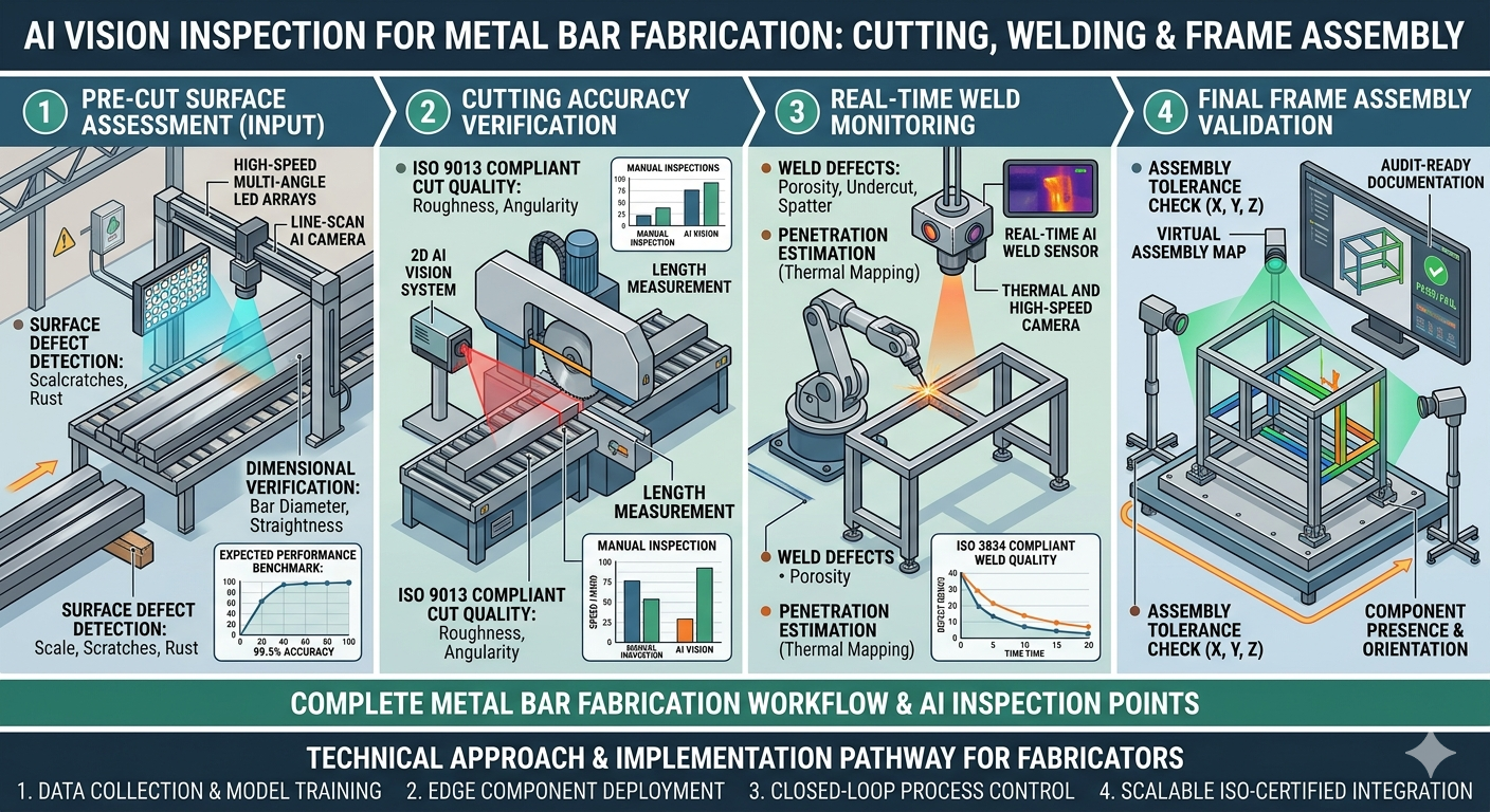
Qualitas Technologies deploys a multi-station architecture that follows the bar through the fabrication line. Station 01 (Pre-Cutting Surface Inspection) uses high-resolution line-scan cameras with coaxial LED illumination to image every bar before it is cut. Coaxial lighting is chosen specifically because it cancels the specular reflections that plague polished or semi-polished stock, making surface cracks, dents, and pitting visible to a CNN-based classifier running at millisecond-scale inference — fast enough to keep pace with line speed, though the exact latency depends on the trained model, image resolution, and controller hardware selected for a given project.
Station 02 (Cutting Accuracy Verification) pairs an area-scan camera with laser triangulation to measure cut offset, centre deviation, and edge quality against the tolerance classes defined in ISO 9013, the international standard for geometrical product specification of flame, plasma, and laser thermal cuts. Stations 03 and 04 (In-Process and Post-Weld Inspection) use a Keyence LJ-X8000 series 2D/3D laser profiler, which captures 3,200 points per profile — a published Keyence specification, not a project-specific figure — to measure bead height, width, throat thickness, and leg length as the weld is made.
| Defect / Anomaly | Detection Method | Station |
|---|---|---|
| Surface cracks | Coaxial line-scan imaging | Pre-cut surface station |
| Dents and deformation | Structured-light 3D profiling | Pre-cut surface station |
| Cut offset / misalignment | Laser triangulation + area camera, checked against ISO 9013 tolerance classes | Post-cut dimensional station |
| Weld porosity / spatter | Keyence LJ-X8000 3D laser profiler, inline | In-process weld station |
| Weld cracks / undercut | Keyence LJ-X8000 profile data + Qualitas AI classifier | Post-weld inspection station |
| Incomplete fusion / overlap | LJ-X8000 bead profile + deep-learning defect model | Post-weld inspection station |
| Angular deviation / warping | 3D multi-camera angular measurement cell | Final frame assembly station |
Expected Outcomes & ROI
Automating surface, cut, and weld inspection changes the basic economics of quality control: instead of a sampled fraction of joints getting checked between an inspector's other duties, every bar, cut, and weld pass receives the same objective check, at line speed, every shift. That shift from sampling to full coverage is the primary driver of any defect-detection uplift a given fabricator sees — the actual percentage increase depends entirely on how much of a shop's current inspection is already sampled, so we don't quote a single fabrication-wide figure here; it gets established against a customer's own baseline during the feasibility review.
- Published deep-learning weld-defect classification research reports accuracy in the 90–99% range on labelled benchmark datasets such as RIAWELC and GDXray for categories like porosity, cracks, and undercut — with the same studies showing accuracy on noisier, real production imagery well below that ceiling, which is why model validation against a customer's own weld population, not a public benchmark score, determines what a deployed system actually achieves.
- 100% in-line inspection at production speed, replacing sampled manual checks with full-coverage automated ones.
- Every weld pass and cut recorded with metadata — batch, timestamp, camera ID, model version — supporting the documentation and traceability expectations behind ISO 3834 quality levels.
- Rework-cost reduction and payback period are highly sensitive to a site's current defect rate, scrap cost, and production volume; these get quantified during the feasibility assessment rather than assumed up front.
Implementation Considerations
Phase 1 begins at the highest-risk station — the weld cell. Phase 2 adds pre-cut surface inspection and cutting accuracy verification, integrating output from all stations into a shared traceability layer. Phase 3 brings in final frame assembly angle checking. Each phase is implemented without halting production using shadow-mode operation, where the vision system runs alongside existing inspection before it is trusted to gate parts on its own.